Ground-Mounted Solar Structures
Last Updated: November 2026
Supplemental Guidance to ASCE Manual 162 for Hot-dip Galvanized Piles and Ground Screws Used in Ground-Mounted Solar Structures
Introduction
The American Galvanizers Association (AGA) supports project-specific corrosion assessment for driven piles, ground screws, and other steel elements used in ground-mounted solar structures. Hot-dip galvanized (HDG) steel is a practical and durable corrosion protection system, but its expected performance depends on the coating thickness and the soil conditions encountered across the site. AGA’s position is that representative site data, an HDG-specific service-life method, and documented engineering judgment should be used during design to support planning and informed decision-making. These practices help project teams specify HDG appropriately for site conditions, supporting expected performance while avoiding surprises.
HDG Benefits in the Solar Market
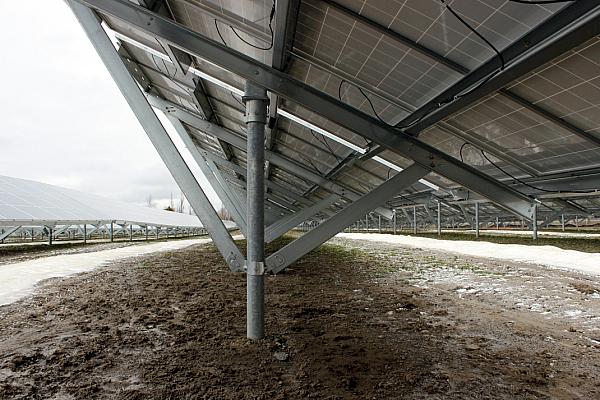
Utility-scale solar projects use large numbers of repetitive steel components over sites that may cover hundreds or thousands of acres. HDG protects these components with a metallurgically bonded zinc coating that provides long lasting corrosion protection. Unlike a simple steel corrosion allowance, the zinc coating delays the onset of base-steel corrosion, proving a reliable and cost-effective way to reduce corrosion risk with little maintenance1. This is supported by the many well-established and proven uses of galvanized steel in soil-contact applications, including reinforced earth, buried steel bridges, buried utility poles, buried guardrail posts, bridge piling, and retaining walls. Coating life is directly related to zinc thickness: when other conditions are equal, a thicker zinc coating provides a longer period of protection. However, HDG performance varies with soil conditions. In very acidic, highly saline, persistently wet, poorly drained, organic, or microbiologically active environments, zinc corrosion rates can increase. Representative site data paired with a practical corrosion model allows engineers to recognize these conditions early and estimate a reasonable range of galvanized coating life for design purposes.
Better and More Consistent Assessment Is Needed
The release of ASCE Manual of Practice No. 162, Design and Construction of Solar PV Structures, is an important step forward for the solar industry2. AGA agrees with the Manual’s recognition that corrosion is an engineering design issue, that soil resistivity alone is not sufficient to estimate corrosion rates, and that project teams should obtain representative soil corrosivity information before finalizing structural design recommendations.
Cost is a practical concern for all projects and the current competitive commercial environment creates pressure to economize and reduce costs associated with site characterization. This means solar foundation decisions are made from a limited geotechnical data set, even though buried-metal corrosion is influenced by several interacting factors and some large solar fields have been known to be highly variable. Topography, drainage, groundwater, agricultural history, imported fill, former wetlands, salts, and organics can create localized conditions that differ from a site average.
AGA supports ASCE’s recommendations on minimum sampling frequency and broader guidance for ensuring the results are representative of the solar field within reason and using engineering judgement in the assessment to optimize cost. Insufficient sampling or an incomplete assessment can make bare steel and HDG appear to perform similarly, suggest that HDG or additional material is unnecessary when it is needed, or overstate site aggressiveness and add avoidable cost.
The geotechnical report should include the following parameters to evaluate below-grade corrosion of galvanized steel and apply zinc corrosion models. Resistivity alone is not sufficient to characterize soil corrosivity2,3.
- pH
- Moisture content
- Chloride content
- Sulfate content
- Sulfide content
- Redox potential
- Resistivity
- Fines content
- Organic matter content
- Presence of anthropic refill areas
Benefits and Limitations of Zinc Corrosion Models
The variety of soil-corrosion models can create uncertainty about which is appropriate for estimating zinc corrosion rates. All corrosion models have value when used within their intended scope. The concern is that models developed for one purpose are often applied to solar PV foundations without explaining their assumptions, limitations, or relationship to HDG performance in soils. No available model describing the performance of zinc in soil can characterize every condition across a large solar field or provide a deterministic guarantee of service life. Instead, corrosion models are most useful as screening and design planning tools. In many cases, experience with similar soil types in other applications is the most reliable indication of likely performance.
Project teams should avoid running multiple models and selecting the preferred answer. First identify what each method predicts, the material and application on which it was based, and whether the project inputs fall within its limits. Differences should prompt a review of the data, assumptions, and consequences and not selection of a different model to obtain a preferred result.
A few of the common corrosion models and approaches for zinc in soil referenced by N. American specifiers include:
AGA HDG in Soil Performance Charts: These charts were developed from real-world galvanized steel exposure data from 122 sites and consider the variables known to have the most profound influence on zinc corrosion rates in soil: chloride concentration, moisture content, and pH4,5. In 2026, AGA revised the charts to report only the time to zinc coating consumption. The charts provide a practical basis for estimating zinc coating life when project data fall within the chart categories. Their principal limitation is the natural spread in the underlying field data. The high, low, and average curves show the range observed within a soil category; they are not precision boundaries and should not be extrapolated beyond the chart. More information is available from AGA regarding interpretation of the chart and an order of operations for determining which chart to use4.
Romanoff (1957, 1962) and King (1977) approach: These studies established pH and resistivity as practical indicators of soil corrosion potential, supported by broad field data and simple application6,7. Relatively few zinc coated samples were evaluated. With this approach it is difficult to capture variability across a large solar site or the influence of other variables known to influence corrosion rate. Simplified pH–resistivity curves may support initial screening or sensitivity analysis, but applying them to a specific project requires engineering judgment and site-specific data2. Such curves are not considered dependable for use in design according to a 2023 National Academies report3.
Elias (1990) and AASHTO approach: This FHWA-developed durability model was largely formalized through a Mechanically Stabilized Earth (MSE) wall research program and then adopted by AASHTO8. It was developed primarily to provide a conservative durability design for galvanized reinforcement in mechanically stabilized earth systems using controlled select backfill. The purpose is not to predict a site-specific zinc corrosion rate. The model is useful within that context and can therefore provide a very conservative sensitivity check. Solar piles are normally installed in native or minimally modified soil over a large and variable site. Applying an MSE backfill method directly to solar foundations can therefore obscure important differences in exposure and in the purpose of the calculation.
pH and resistivity methods for corrugated steel pipe (CSP): Methods published in commonly cited culvert standards and guidance, including AISI and NCSPA guidance documents, were developed to support material selection and service-life design for galvanized corrugated steel pipe9. These methods use pH and minimum resistivity as primary indicators of environmental corrosivity. AISI and NCSPA charts evaluate average invert life for galvanized CSP, defined as the predicted time until the pipe's bottom section (the invert) reaches an average metal loss limit of 25%. These models may provide a useful sensitivity check when project conditions fall outside the AGA charts or when pH and resistivity indicate unusually aggressive conditions.
Suggested Approach
When the required inputs are available and site conditions fall within their scope, the AGA HDG Performance in Soil charts provide a practical starting point for evaluating HDG coating life. Determine the applicable chart category and consider the average, high, and low field-performance curves as a range. It is not possible to extrapolate downward from the red line or upward from the blue line with any degree of accuracy.
Because coating thickness is directly proportional to service life, clearly state the assumed galvanized coating thickness as determined using the applicable galvanizing specification such as ASTM A123/A123M10. To address uncertainty in an assessment, a thicker galvanized coating can be specified if the viability of a thicker coating has been evaluated and agreed with the manufacturer/galvanizer.
Sometimes project conditions fall outside the AGA charts, such as very low pH combined with high moisture or chlorides. For such cases, consider additional site data, a Romanoff similitude analysis performed by a corrosion specialist, project-specific testing, or other strategies.
Other methods may be used to test sensitivity or identify whether the selected result is unusually high or low. Confirm the units and input data; identify whether the model addresses zinc, steel, pitting, average loss, or first perforation; check whether it assumes native soil or controlled backfill; and review whether project conditions are within the model’s range. Resolve the difference through engineering judgment and, if needed, additional data.
Conclusion
By applying this guidance, project teams can better account for site conditions, select appropriate evaluation methods, and make informed design decisions that help realize the durability, reliability, and cost benefits of HDG in solar foundation applications.
References and Supporting Resources
- Zhang, X. G. “Corrosion in Soil,” in Corrosion and Electrochemistry of Zinc.
- American Society of Civil Engineers. Design and Construction of Solar PV Structures, Manual of Practice No. 162, 2026.
- National Academies of Sciences, Engineering, and Medicine. 2023. Corrosion of Buried Steel at New and In-Service Infrastructure. Washington, DC: The National Academies Press.
- American Galvanizers Association. The Service Life of Galvanized Steel Articles in Soil Applications.
- Padilla, V., Ghods, P., and Alfantazi, A. “Parametric Studies and Application of a Practical Model for Corrosion of Galvanized Steel in Soil.” Corrosion, Vol. 70, No. 12, 2014.
- Romanoff, M. Underground Corrosion. National Bureau of Standards Circular 579, 1957.
- King, R. A. (1977). A review of soil corrosiveness with particular reference to reinforced earth (Supplementary Report 316). Transport and Road Research Laboratory.
- Elias, V., et al. Corrosion/Degradation of Soil Reinforcements for Mechanically Stabilized Earth Walls and Reinforced Soil Slopes. FHWA-NHI-09-087.
- National Corrugated Steel Pipe Association. Pipe Selection and Service Life Guide. NCSPA, 2025
- ASTM A123/A123M, Standard Specification for Zinc (Hot-Dip Galvanized) Coatings on Iron and Steel Products.