
Oversized Fabrications and Hot-Dip Galvanizing: How to Design for Success

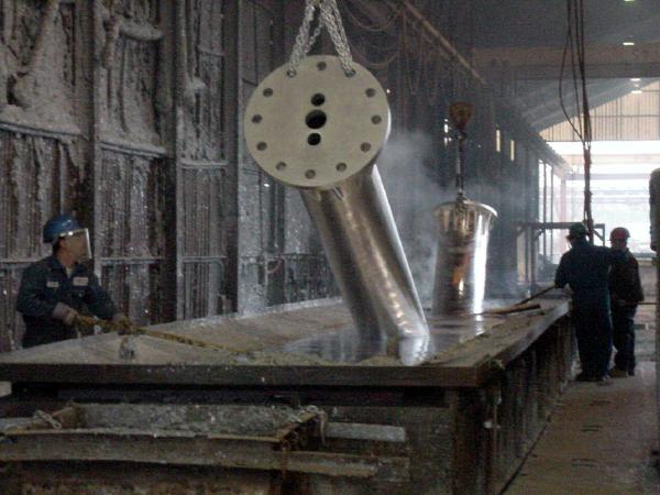
“Maximum size” for oversized hot-dip galvanizing (HDG) is set by the galvanizing kettle’s usable length, width, and depth, plus the plant’s ability to rig and manipulate the fabrication safely at a workable immersion angle. If the part fits in the kettle on paper but the crane cannot lift, rotate, or clear the building, the item cannot be galvanized.
Use the AGA’s Galvanizer Locator to see if nearby kettles can accommodate your design. We do however, always recommend discussing a close fit with the galvanizer. Nobody knows their kettle and plant capacities better than the galvanizer, and many have found creative ways to accommodate awkward or oversized pieces using depth, diagonal positioning, and kettle corners.
Kettle length, width, and depth are the hard geometric limits because hot-dip galvanizing is a complete immersion process, and the part must physically fit into the molten zinc bath. AGA guidance cites typical North American kettle sizes in the range of 30-60 ft (9-18 m) length, 5-8 ft (1.5-2.4 m) width, and 6-12 ft (1.8-3.6 m) depth. Those numbers matter because they let you screen feasibility at concept stage before you spend hours detailing stiffeners, copes, and hole patterns.
A galvanizer also faces practical handling constraints that may not be apparent in the design model:
- Crane capacity and hook height that control whether the plant can pick the assembly weight and still achieve the required dip angle.
- Rigging height and sling geometry that determine whether the high end of a long piece can clear the kettle rim without binding.
- Building and bay clearances such as door height, roof trusses, and travel limits on the bridge crane that restrict rotation and travel paths.
How do you screen large designs early to avoid delays?
Screen oversized HDG designs by considering plant limits first, then validating fit, dip orientation, and vent/drain intent before you release detailing. Engineers who run this screen at 30-60% design avoid the common “rework loop” where venting, lifting, and split lines get decided after procurement.
Early coordination between the designer, fabricator, and galvanizer remains one of the most effective ways to avoid costly redesigns. Reviewing large or unusually shaped assemblies with the galvanizer during design development often identifies handling, venting, drainage, and immersion concerns before fabrication begins.
- Request plant limitations early. AGA points to tools such as the AGA Galvanizer Locator to identify facilities and start those discussions, but you may still need plant-specific numbers obtained by directly contacting the galvanizer.
- Check “diagonal fit” and end-clearance assumptions with the plant. Your CAD check should match how galvanizers actually load. Many oversized pieces rely on corner-to-corner positioning or immersion at an angle. Confirm two items with the galvanizer: the usable kettle dimensions, not nominal dimensions.
- Use AGA progressive dip charts to estimate feasible length. If the length exceeds single-dip capacity, estimate progressive-dip feasibility with the AGA Progressive Dip Charts and confirm the result with the plant. The charts relate kettle depth and article height to maximum achievable length during progressive dipping. AGA provides an example that anchors the magnitude: a 2 ft high article in a 40 ft long and 6 ft deep kettle can be progressive dipped to about 61 ft. That delta between kettle length and achievable coated length often decides whether you modularize or keep the assembly intact.
- Validate vent/drain paths for the proposed dip orientation. Venting and drainage are not a generic checklist item on large fabrications. Your dip orientation decides where zinc must enter, where air must escape, and where zinc must drain. The AGA Design Guide emphasizes placing holes in end plates, stiffeners, webs, and other features so molten zinc can flow freely over all surfaces, including internal compartments. On a large box, your team can model the assembly as a set of “rising” and “falling” pockets at the intended tilt and then place vents near high points and drains near low points. When design constraints prevent ideal venting, consult the galvanizer rather than forcing a compromised pattern into released drawings.
- Fit includes rigging height and safe manipulation, not only kettle length. A 36 ft member that “fits” by diagonal geometry can still fail if the crane cannot rotate it without striking roof steel or if the sling angle crushes thin gussets.
When the part is too large for full immersion, what are the alternative options?
Common solutions include modularization, progressive dipping, and hybrid coating systems. The most appropriate option depends on project geometry, handling constraints, performance requirements, appearance expectations, and construction considerations. Your best choice depends on which risk you can control: connection complexity, coating continuity, or field work.
Option |
Risk profile (technical) |
Cost drivers (where money moves) |
Schedule impacts (typical failure mode) |
Modularization |
Lower galvanizing process risk because each module is designed to fit standard kettle handling. |
Added splice plates, more bolts, more shop fit-up hours, and extra shipping skids. |
Field assembly sequencing and access constraints can drive delays if lifts or tolerances go unmanaged. |
Progressive dip |
Risk is concentrated in overlap zone planning, symmetry, vent/drain performance, and distortion potential. |
Fewer splices than modularization; plant may charge for special handling and process time. |
Rework risk shows up when the overlap falls on a connection surface or inside a tight tolerance zone. |
Hybrid coating |
Risk shifts to coating specification, surface preparation control, and inspection acceptance criteria. |
Cost moves into surface preparation and coating QA; HDG savings remain on smaller pieces. |
Submittal cycles and coating contractor availability can extend procurement if not planned at bid stage. |
Modular Design
Almost any component can be galvanized by designing and fabricating in modules or sub-units suitable for available galvanizing facilities. Designing structures in modules or sub-units to accommodate the galvanizing kettle often provides additional savings in manufacturing and assembly because they simplify handling and transportation. The sub-units can be connected after galvanizing by bolting or field-welding.
Progressive Dip
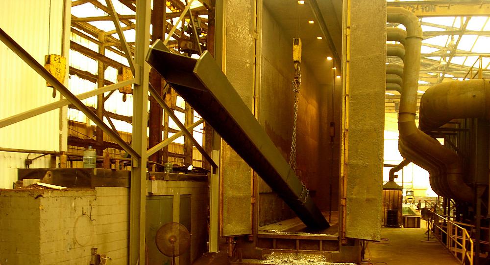
Progressive dipping basics matter because it sounds simple in a meeting and becomes complex in detailing. The galvanizer immerses one end, withdraws, then immerses the other end to coat the full length. Progressive dipping should always be evaluated in consultation with the galvanizer because feasible immersion angles, overlap locations, handling methods, and distortion risks vary by facility.
Another consideration with progressive dipping is the overlap zone, which can create a visible line where the two dips meet. The line is cosmetic and weathers over time, but engineers still need to keep that zone clear of bearing surfaces, slip-critical faying surfaces, or architecturally exposed locations where the owner will reject a visible transition.
For additional information on progressive dipping see The Progressive Dip Process, and for context on constraints and overlap planning, use Considerations for Progressive Dipping.
Hybrid Coating
For projects containing a mixture of components suitable and unsuitable for hot-dip galvanizing due to size, a hybrid coating of HDG and thermal spray zinc (otherwise known as TSZ or zinc metallizing) should be considered for maximum cost efficiencies while leveraging the benefits of both coatings.
On a practical level, this could mean hot-dip galvanizing smaller or more complex components of a project that fit within the kettle while zinc metallizing those components that are too large, but otherwise have accessible surfaces for zinc metallizing application. It could also mean hot-dip galvanizing each end of an oversized item via progressive dip, and zinc metalizing any mid portion which was unable to be galvanized due to size. The AGA offers specific guidance in the publication Hybrid Zinc Coatings: Specifying HDG + TSZ to identify the components on a project that are ideal candidates for hot-dip galvanizing, thermal spray zinc and/or a hybrid solution using both.
Putting oversized HDG into practice: a pre-fabrication checklist designers can issue
Before you send IFC drawings, issue a one-page oversized HDG checklist with the bid package or as a design deliverable. Teams who do this reduce the number of galvanizing RFIs that arrive after steel is cut.
- Confirm kettle dimensions, crane limits, and allowable dip orientations with the selected galvanizer.
- Identify the oversized strategy early: modular, progressive dip, or hybrid coating, and show the intended split or overlap zones on the GA drawings.
- Document vent/drain intent on drawings and include lifting points and any temporary bracing notes for open or flexible frames, consistent with AGA handling guidance.
- Send GA details to the galvanizer pre-bid or pre-release so the plant can review fit assumptions, rigging approach, and vent/drain routing before your fabricator commits to shop hours.