Warpage and Distortion
What measures can be taken to reduce the potential for warpage/distortion?

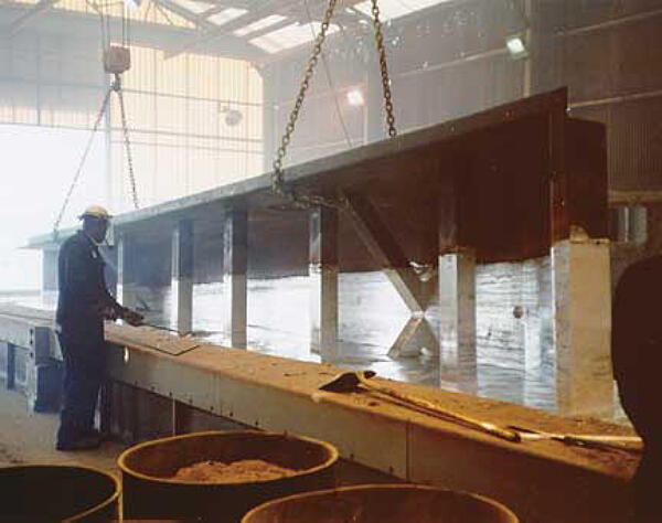
Some fabricated structures and assemblies may distort at the galvanizing temperature as a result of relieving stresses induced during steel production and in subsequent fabricating operations. In general, the potential for warpage/distortion can be greatly reduced through design and production engineering measures to avoid high internal stresses. The best prevention is to start discussions between the designer, fabricator, and galvanizer at an early stage in the design process so that good design features can be incorporated.
Inherent Stresses Within Steel
- The most commonly distorted members of assemblies is that of sheet or plate which is ¼ in thickness or less the lighter the gauge of the steel, the greater the risk of warpage/distortion.
- Flatten sheet/plate using a jig or by weighing the product down on a flat surface during cool-down.
Internal Stresses Induced By Cold Working
- Optimize design to reduce punched holes, rolling, riveting, bending, and straightening.
- Bend members to the largest acceptable radii to minimize local stress concentration.
- Stress relieve assemblies per ASTM A143 where excessive cold-working cannot be avoided.
- Air cool to minimize stress from the cooling cycle.
Welding Before Hot-Dip Galvanizing
- Avoid specifying joint designs or weld lengths which are greater than statically required.
- Place welds near to and symmetrically around the neutral axis - align welds so shrinkage and opposing forces are balanced rather than all pulling in the same direction.
- Minimize welding by using bolted connections or performing assembly after hot-dip galvanizing.
- Specify the installation of diagonal members to be performed after galvanizing.
- Develop a welding sequence plan to be adhered to during fabrication:
- Weld the assembly from inside to outside to avoid high shrinking stresses.
- Avoid the need to force, spring, or restrain components during welding.
- Avoid over-welding and use as few weld passes as possible.
- Continuously weld thick sections; however, thin sections may benefit from staggered welding. For staggered welding of 1/8 in or lighter material, weld centers should be closer than 4 in.
Asymmetrical Design
- Specify symmetrically rolled sections instead of angle or channel frames.
- Assemble two asymmetrical sections back-to-back using temporary bracing and spacers to create a symmetrical section.
- Install temporary bracings for curved plates, channel frames, and troughs which are proportional to plate thickness; located at quarter points of product height.
- Tees should be dipped flange-side first while channels should be dipped web-side first.
- Perform immersion as quick as possible and at the largest possible dip angle.
Thin and Thick Material Within Assembly
- Steel thicknesses should vary as little as possible throughout the assembly.
- Add stiffeners to the design of structures containing unsupported flat sheets.
- Flange-to-web thickness of fabricated beams should be no more than 3 to 1.
- Galvanize thick and thin portions separately and join them after galvanizing.
- Perform immersion as quick as possible and at the largest possible dip angle.

Progressive Dipping
- Consult with the galvanizer to take into account length variations of the assembly and plan for thermal expansion conditions.
Poor Drainage/Venting and Lifting Points
- Lift points for galvanizing should be located at quarter points along the product length.
- Design drainage/venting holes per ASTM A385 and maximize drainage for hollow sections.
Long Immersion Time
- Steel should not be left in the molten zinc bath any longer than necessary to avoid relieving additional internal stresses.
Poor Laydown After Galvanizing
- Arrange products flat and free from external forces during the cool-down phase.
- Use additional supports underneath the mid-section of products to prevent sagging.
- To support a positive or negative camber, lay the product on the strong axis and support with as many blocks as possible.
As always, the most effective way to deal with warpage and distortion of hot-dip galvanized parts is to reduce risks during the design stages. The following steps should be taken during the design stage to minimize the chance of warpage and distortion.
- Where possible, use symmetrically rolled sections in preference to angle or channel frames. I-beams are preferred to angles or channels.
- Use parts in an assembly of equal or near equal thickness, especially at joints.
- Use temporary bracing or reinforcing on thin-walled and asymmetrical designs.
- Bend members to the largest acceptable radii to minimize local stress concentration.
- Accurately pre-form members of an assembly so it is not necessary to force, spring, or bend them into position during joining. Continuously weld joints using balanced welding techniques to reduce uneven thermal stresses. Pinholes from welding are very dangerous in items to be galvanized and must be avoided. Staggered welding techniques to produce a structural weld are acceptable. For staggered welding of 1/8-inch (4 mm) or lighter material, weld centers should be closer than 4 inches (10 cm).
- Avoid designs that require progressive dip galvanizing. It is preferable to build assemblies and subassemblies in suitable modules so they can be immersed quickly and galvanized in a single dip. In this way, the entire fabrication can expand and contract uniformly. Where progressive dipping is required, consult your galvanizer.
Theres also an option to make an asymmetrical piece into a symmetrical shape. The unrecoverable beam we saw before, for example, could have been made more symmetrical by welding a similar U-shaped piece to the bottom as well as the top. This could cause the internal stresses in the bath to counteract each other and prevent the piece from warping.
© 2026 American Galvanizers Association. The material provided herein has been developed to provide accurate and authoritative information about after-fabrication hot-dip galvanized steel. This material provides general information only and is not intended as a substitute for competent professional examination and verification as to suitability and applicability. The information provided herein is not intended as a representation or warranty on the part of the AGA. Anyone making use of this information assumes all liability arising from such use.

