Venting and Drainage Holes in Square and Circular Tubular Assemblies

When galvanizing hollow fabrications, ASTM A385 contains the primary information on the minimum openings and locations for vent and drain holes to prevent air from being trapped during immersion in cleaning solutions or molten zinc. Additionally, figures are provided for clarity to describe some common conditions encountered with tubular product assemblies such as columns with base plates (Figure 1).
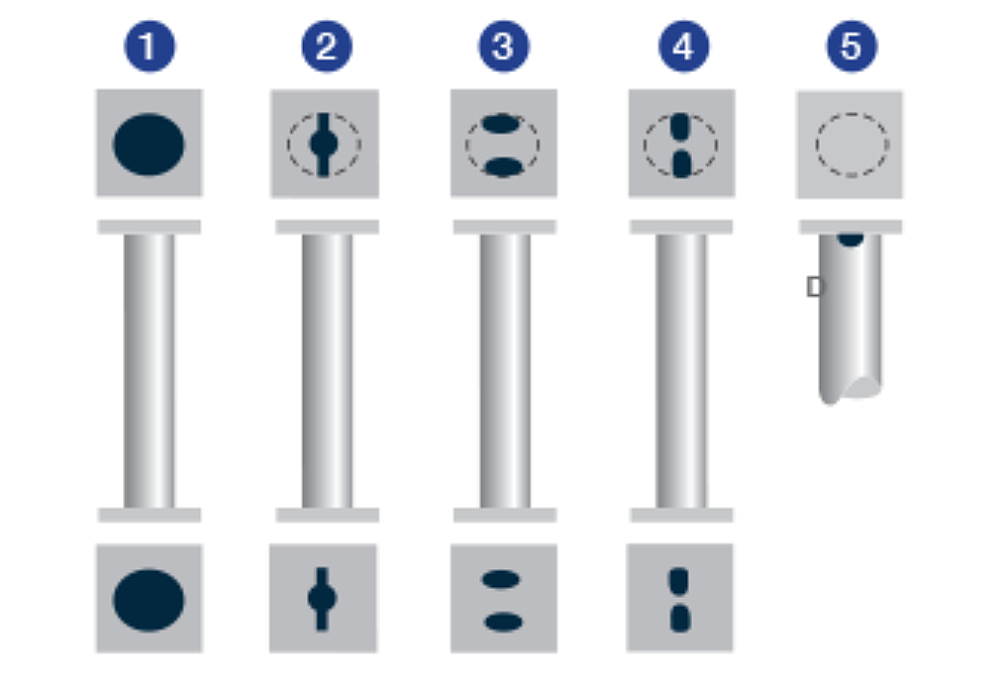
However, if a full opening is not allowed, it is incorrect to assume the vent and drain hole design substitutes provided in ASTM A385 for round tube/pipe with base plate (Figure 1) will provide adequate venting and drainage for square hollow and rectangular hollow structures with base plates. This is due to a difference in geometry when the parts are hung at an angle for immersion in the galvanizing process tanks.
The internal corners of square and rectangular assemblies have a tendency to trap air in the high point of corners and cleaning solution or molten zinc in the lowest point of corners. The best practices for venting and drainage hole placement are to ensure vent holes are located at the highest possible point and drain holes at the lowest possible point, square and rectangular assemblies make this difficult since the highest and lowest points can change depending on how they are hung prior to surface prep and immersion. When square or rectangular tubing is lifted, the angles and slopes created can oftentimes cause the highest point to shift while circular assemblies are more forgiving. Since the crane operator cannot control the orientation of each individual tube, a different approach is necessary to accommodate designs with corners to avoid bare spots, zinc entrapment, or creating a potentially dangerous situation (blowout).
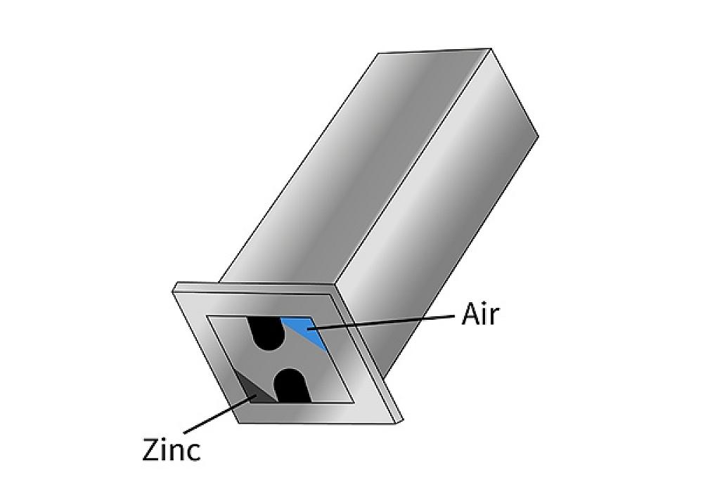
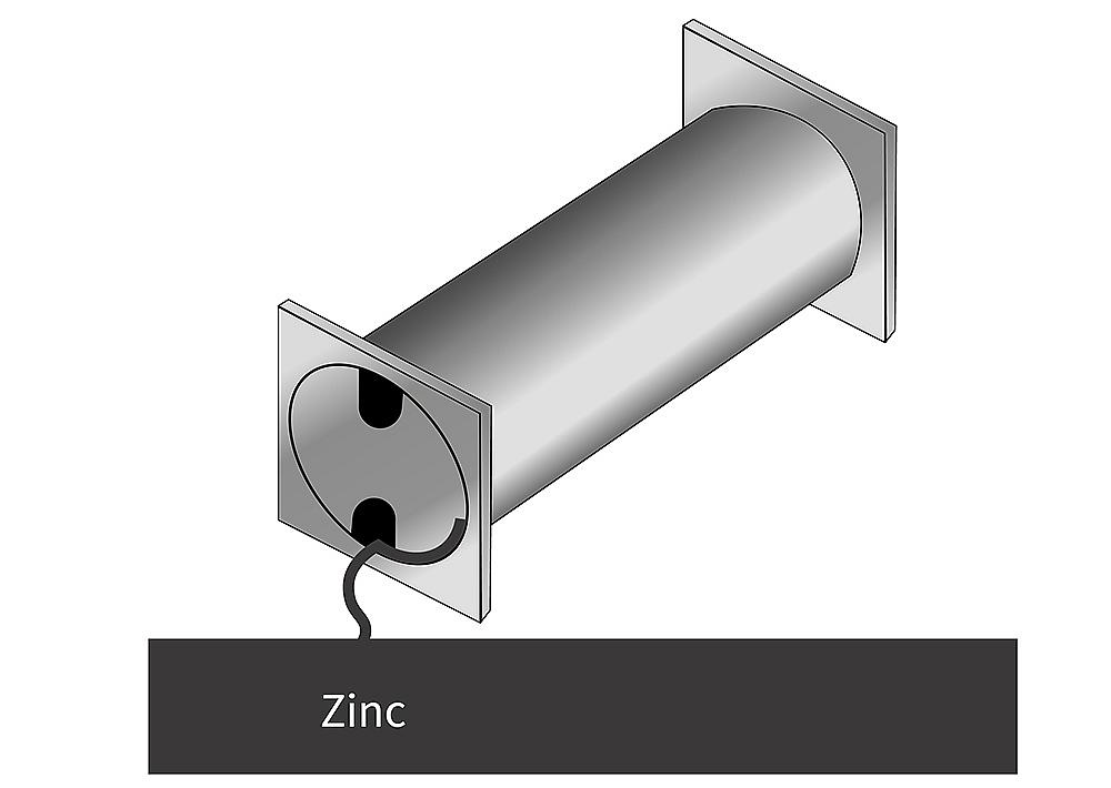
For example, occasionally there are questions as to why the keyhole or oval-shaped detail options are appropriate for circular columns but not for square or rectangular columns. Figure 2 illustrates how corners tend to trap air, zinc, and other solutions which is the chief concern behind the additional requirements. Figure 3 shows how circular assemblies are more forgiving due to their free-flowing design.
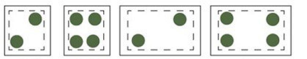
To assist specifiers and detailers, AGA publishes specific guidance on Rectangular and Square HSS Venting & Drainage details for times when fully open ends cannot be accommodated by the design. The use of a 2-hole or 4-hole design in the corners addresses the geometry specific to square/rectangular parts, however the 4-hole design is preferred for an improved finish and because it allows the most flexibility when orienting the parts for lifting during the galvanizing process.
© 2026 American Galvanizers Association. The material provided herein has been developed to provide accurate and authoritative information about after-fabrication hot-dip galvanized steel. This material provides general information only and is not intended as a substitute for competent professional examination and verification as to suitability and applicability. The information provided herein is not intended as a representation or warranty on the part of the AGA. Anyone making use of this information assumes all liability arising from such use.