Asymmetrical Design and Preventing Warpage/Distortion

How does asymmetrical design affect the potential for warpage and distortion?
Galvanized steel is exposed to a wide temperature range from room temperature to 850 F. Because parts are immersed at an angle and may vary in thickness, uneven heating and cooling occurs. This exposure to temperature variations allows the steels internal stresses that have been introduced by either design or fabrication to be relieved at different times, potentially resulting in warped or distorted structures.
As advised within ASTM A384 Practice for Safeguarding Against Warpage and Distortion During Hot-Dip Galvanizing of Steel Assemblies, the potential for warpage and distortion is greatly reduced when a product is symmetrical about its horizontal and vertical axes in shape, material, and overall weld design. Symmetrical sections such as I-beams and tubing will be less likely to distort than asymmetrical pieces (camber beams, channels, tees, custom beams, girders) because the thermal expansion forces above and below the natural axes balance each other. Conversely, the internal stresses in asymmetrical designs will be relieved unevenly due to the constraints of the materials shape.
Let us take a look at four examples where asymmetrical design resulted in warpage and distortion.
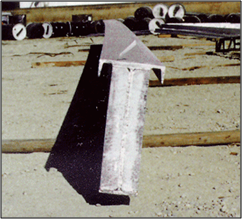
The design of the part in Figure 1 includes a top flange from channel material but has no corresponding bottom flange to make the design symmetric. This allows the buildup of stress during the thermal expansion of the part in the galvanizing kettle to be relieved by distorting the entire piece from one end to the other, following the most likely rolling direction of the steel used for the web portion of this part.
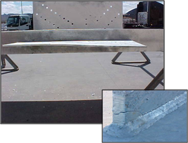
Figure 2 shows a fabrication where a plate was welded to the side of a beam. When this fabrication was brought up to galvanizing temperature, the thermal expansion proceeded at different rates for the beam and the plate. This put considerable stress on the plate as it tried to expand more rapidly than the beam, however, the welding together of the two materials did not allow for separate movement. Since the plate material cannot move near the weld joint, it relieved the stress build-up by distorting away from the weld joint and cracking the weld joint.
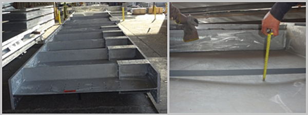
The design of the fabrication in Figure 3 was problematic because of asymmetry in the distribution of material and the overall welding design. Additionally, a thin plate was constrained between two thicker plates by welding. When this assembly reached galvanizing temperature, the thin plate expanded more rapidly than the surrounding materials. The amount of welding and material on either side of the plate unevenly constrained the movement of the thin plate, and the additional stress was relieved through buckling of the plate up to one inch as shown in the picture on the right.
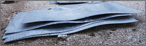
The checkered/diamond plate shown in Figure 4 distorted during galvanizing as a result of the asymmetry of the plate design (as the raised pattern is only on one side of the material) and the stress induced by stamping of the material during fabrication. Additionally, the thinner the checkered plating, the greater the risk of distortion.
The best way to prevent warpage and distortion is to follow the recommended design practices within ASTM A384, however, asymmetrical designs can be successfully hot-dip galvanized. Warpage and distortion as a result of galvanizing asymmetrical sections can be prevented in three ways:
- Fabricate and galvanize symmetrical components of the section separately and assemble after galvanizing.
- When working with several identical asymmetrical pieces, assemble two sections back-to-back using temporary bracing and spacers to create a symmetrical section. Once the part has cooled, remove bracing and touch up the bare area from the spacers according to ASTM A780.
- Redesign the section to make it symmetrical.
© 2026 American Galvanizers Association. The material provided herein has been developed to provide accurate and authoritative information about after-fabrication hot-dip galvanized steel. This material provides general information only and is not intended as a substitute for competent professional examination and verification as to suitability and applicability. The information provided herein is not intended as a representation or warranty on the part of the AGA. Anyone making use of this information assumes all liability arising from such use.