Design Details and Fabrication Best Practices for HDG
The overall design of parts before fabrication is a primary factor in the initial galvanized finish. Many recommended design details for improving quality of the hot-dip galvanized coating are provided within ASTM A385 Standard Practice for Providing High-Quality Zinc Coatings (Hot-Dip). However, this standard is intended for general galvanizing purposes and additional requirements are necessary to achieve elevated aesthetics for AESS members. When specified in addition to ASTM A385, the following design and fabrication best practices allow the galvanizer to successfully implement process changes to maximize aesthetics while minimizing the time and cost of the surface smoothing to be performed after galvanizing.
Most iron-containing materials are suitable for galvanizing, but steel selection has the greatest influence on the hot-dip galvanized coating aesthetics and quality. Trace elements in the steel affect the thickness, structure, appearance, and overall quality of the galvanized coating. Specifically, steels with silicon or phosphorus levels outside of recommended ranges are known in the galvanizing industry as “reactive steels” and are known to produce thick and/or rough coatings. Reactive steels are galvanized on a regular basis, but the newly galvanized articles often appear matte gray as opposed to a bright and/or spangled appearance common when hot-dip galvanizing steels of recommended chemical composition. Consequently, combining steels of different material thickness, chemistries, or initial surface conditions in an assembly will result in a mixed appearance after hot-dip galvanizing.
Steel Selection
ASTM A385 contains the desired elemental ranges for steel composition to maximize quality for after-fabrication hot-dip galvanizing:
- Silicon levels either less than 0.04% or between 0.15% - 0.22%
- Phosphorus less than 0.04%
- Carbon less than 0.25%
- Manganese less than 1.35%
Although sometimes a reactive steel is desired to achieve greater zinc thickness and longevity of the hot-dip galvanized coating, other times an excessive coating thickness can lead to brittle coatings, poor adhesion and/or surface conditions unacceptable for AESS members. As the steel thickness of any reactive steels increase, or when thick steel (above 2-3 inches) is welded to reactive steels in an assembly, the potential for aesthetic and adhesion concerns increases significantly. Predicting steel reactivity is not an exact science. Element levels can vary +/- 0.02% and the values listed on a mill test report are only one sample taken from the heat. Element levels on individual pieces, and even on the same piece of steel, can vary to some degree. However, mill reports which state the estimated elemental composition typically lead to the most accurate evaluation.
Steel Size
Because hot-dip galvanizing is a total immersion process, the designer should take into consideration any steel parts must fit within the galvanizing bath while being suspended at a steep angle. This may require designing in modules or sub-units for connection by welding or bolting after galvanizing. Steel size limitations are governed by the galvanizing kettle dimensions, but the average kettle length in North America is 40 ft (12 m) and 50-60 ft (16-18 m) kettles are available. It is wise to verify all kettle constraints with your galvanizer early in the design process. Kettle dimensions for all AGA member galvanizers are available at galvanizeit.org/galvanizers.
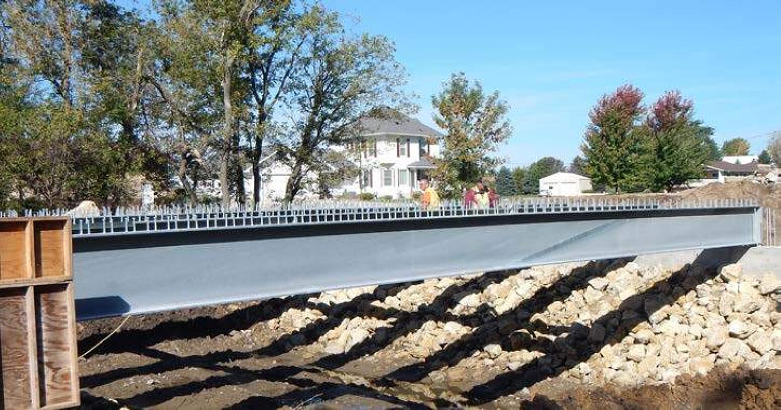
Practical constraints regarding kettle depth should also be considered to significantly reduce time and cost for the surface smoothing of AESS members after hot-dip galvanizing. Natural and solid byproducts of the HDG process known as dross particles develop within the galvanizing bath and gradually settle at the bottom 3-12 inches of the kettle, known as the bottom dross layer. Large parts that reach near the bottom dross layer are more likely to develop rough galvanized coatings containing dross particle inclusions. For parts too large for total immersion in the galvanizing kettle, progressive dipping is a galvanizing method used to immerse each end of the article sequentially to coat the entire item. In practice, progressively dipped articles result in a notably dark and rough overlap area unlikely to weather uniformly over time (Figure 6). As a result, progressive dipping is not a recommended practice for unpainted galvanized AESS expected to meet category 3 or 4 characteristics. For galvanized AESS members that will be painted or powder coated, the excess coating thickness can be successfully buffed or ground down even with the surrounding coating.
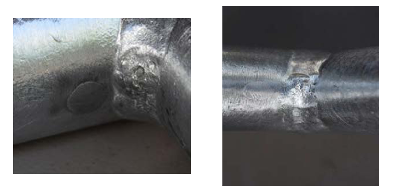
Welding Before Batch HDG
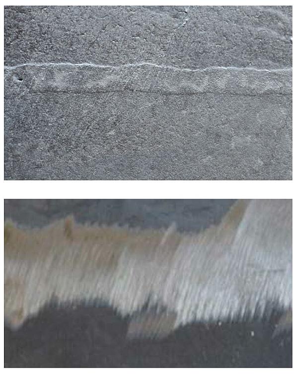
When welded items are galvanized, two factors have the greatest impact on coating quality and aesthetics: cleanliness of the weld area and metallic composition of the weld. Welding slag, flux residues, and welding sprays (with the exception of water-soluble sprays) must be fully removed prior to galvanizing. Welding electrodes high in silicon (>0.25% Si) may cause excessively thick and/or darkened galvanized coatings to form over the weld. When smooth products are welded using high silicon electrodes, the coating over the weld material will be thicker than the surrounding coating, causing a raised weld in an otherwise smooth product. This appearance, sometimes referred to as a “raised weld” or “swollen weld,” will require additional smoothing after galvanizing to meet AESS 3 and 4 characteristics (Figure 7). Specifying ground welds before galvanizing does not successfully prevent this condition, but is still necessary when raised welds are expected to be minimized.
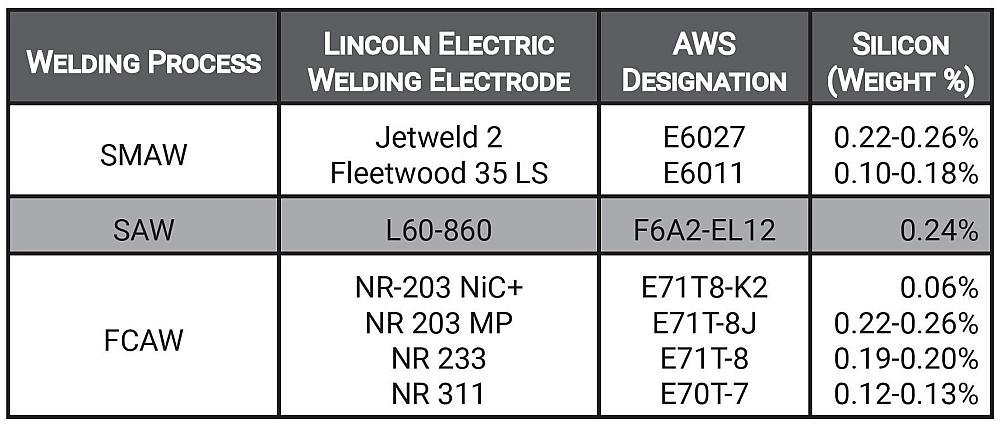
Specify a welding electrode with a chemical composition as close as possible to the parent metal to minimize differences in appearance and potential costs associated smoothing welds after galvanizing. A list of welding electrodes which are known to promote a more uniform appearance are provided in Table 2. In some welding processes (e.g. FCAW-G), the availability of low silicon welding electrodes may be uncommon. When designing for hot-dip galvanizing, the best practice is to avoid overlapping joints with narrow gaps. The resulting gap allows galvanizing pretreatment chemicals to enter, but molten zinc cannot enter gaps less than 3/32-in. Entrapped solutions rapidly expand at galvanizing temperatures and may result in blowout of overlapping areas 16 in2 or greater. Even if blowout is avoided, galvanizing pretreatment chemicals interact with the steel and moisture in the environment and cause rust to eventually bleed from the joint. To ensure structure integrity, galvanizing quality, and aesthetics near overlapped areas, the following methods are suggested:
- Fully seal weld and specify venting of the overlapping area to prevent weld blowout based on steel thickness and size of overlap area (ASTM A385 Tables 1 & 2).
- Intermittent weld, specify a minimum 3/32 in. gap between surfaces and increase weld size as required. One practical method utilizes 3/32 in. stainless steel wire spacers to minimize contact area. Maintaining a gap may become impractical for large areas.
- Where seal welding or stitch welding (described above) are impractical, specify venting of the overlap area to prevent weld blowout (ASTM A385 Table 1 & 2), clean any staining from rust bleeding from the HDG surface, and specify a caulking to seal the joint after galvanizing.
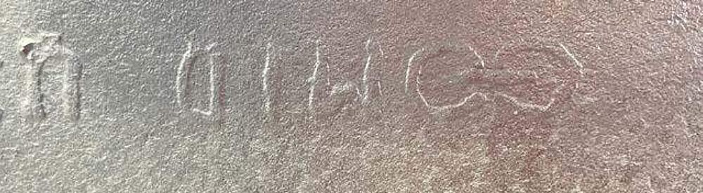
Mill Markings, HSS Seams
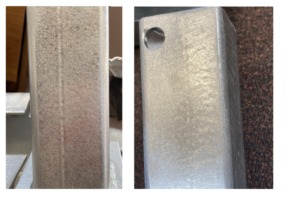
In the galvanizing process, steel interacts with zinc in a diffusion reaction, meaning the coating grows perpendicular to all surfaces at a uniform rate. As a result, any initial imperfections in the steel surface will remain equally visible upon hot-dip galvanizing. For AESS 3 and 4 category requirements, the grinding and filing of HSS seams (Figure 8), mill markings (Figure 9), and other raised surface conditions will minimize their appearance after hot-dip galvanizing but it is unreasonable to expect they will be eliminated. Similarly, any divots or low spots in the steel surface will not be filled.
Especially for showcase elements with all sides exposed, design teams should determine whether seam grinding and smoothing of grinder marks before hot-dip galvanizing is necessary to achieve the desired aesthetic. Use the AESS Custom category characteristic 4.1 to clarify the seam preparation requirement(s), and then clearly specify seam orientations in the design documents. If not clearly indicated, fabricators are encouraged submit an RFI early in the project to determine seam preparation and orientation.
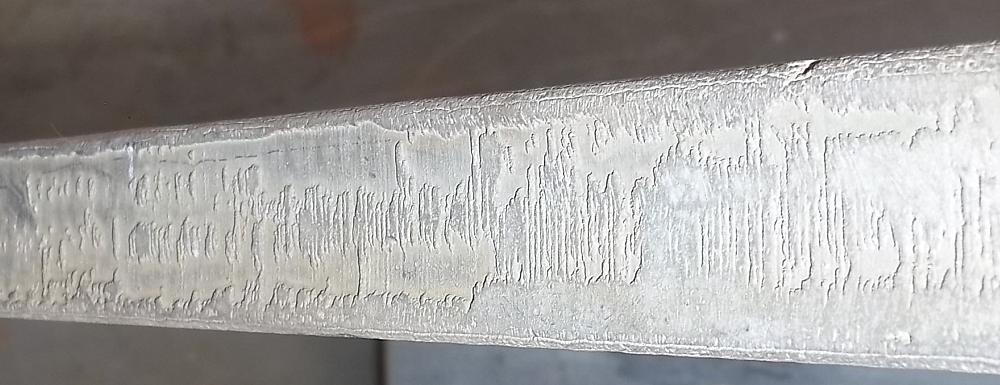
Thermally Cut Edges
Thermal cutting techniques can change the properties of the steel and increase the hardness at the edge of the plate. The increase in hardness changes the diffusion properties of the steel and makes it very difficult to form a galvanized coating of suitable aesthetics for AESS along the cut edge, particularly among flame cut edges on steels greater than ½ in. thick (Figure 10).
To achieve a high quality finish along thermally cut edges, the steps necessary are beyond the capabilities of the galvanizer. The fabricator must ensure the flat surface of all thermally cut edges are ground at least 1/16 in. into the parent material before galvanizing in addition to the grinding of sharp edges as outlined per AESS category requirements. Although grinding of thermally cut surfaces is often considered impractical and significant in terms of fabrication cost, this method is more efficient, cost-effective, and visually appealing compared to remedying the appearance after hot-dip galvanizing.
Designated Lift Points
Specifying designated lift points (temporary or permanent lifting lugs, 5/8 in. diameter holes, etc.) for hot-dip galvanizing allows the galvanizer to lift parts at an angle without the use of chains, thereby avoiding the presence of chain and wire mark indentations in the coating which are very difficult to smooth for increased aesthetics without damage. A fully optimized lifting configuration requires direct communication with the galvanizer and considers an angled lift, the location of venting/drainage holes, and the galvanizer’s plant specific material handling capabilities.
Optimized Venting and Drainage
For successful hot-dip galvanizing, cleaning solutions and molten zinc must flow without undue resistance into, over, through, and out of the fabricated article. The minimum requirements for venting and drainage design details are provided in the standard ASTM A385 Practice for Providing High-Quality Zinc Coatings (Hot-Dip). However, these requirements do not necessarily provide sufficient venting and drainage details to maximize aesthetics for AESS. It is often necessary to specify additional design optimizations to improve quality, avoid bands of light colored oxide lines, and minimize the amount of smoothing and filing after galvanizing.
The larger and more complex the fabrication, the more critical the venting and drainage details are to the overall aesthetics of the part. It is strongly advised to consult directly with the galvanizer to optimize placement, quantity, and size of venting/drainage holes in relation to the handling orientation (Figure 11).
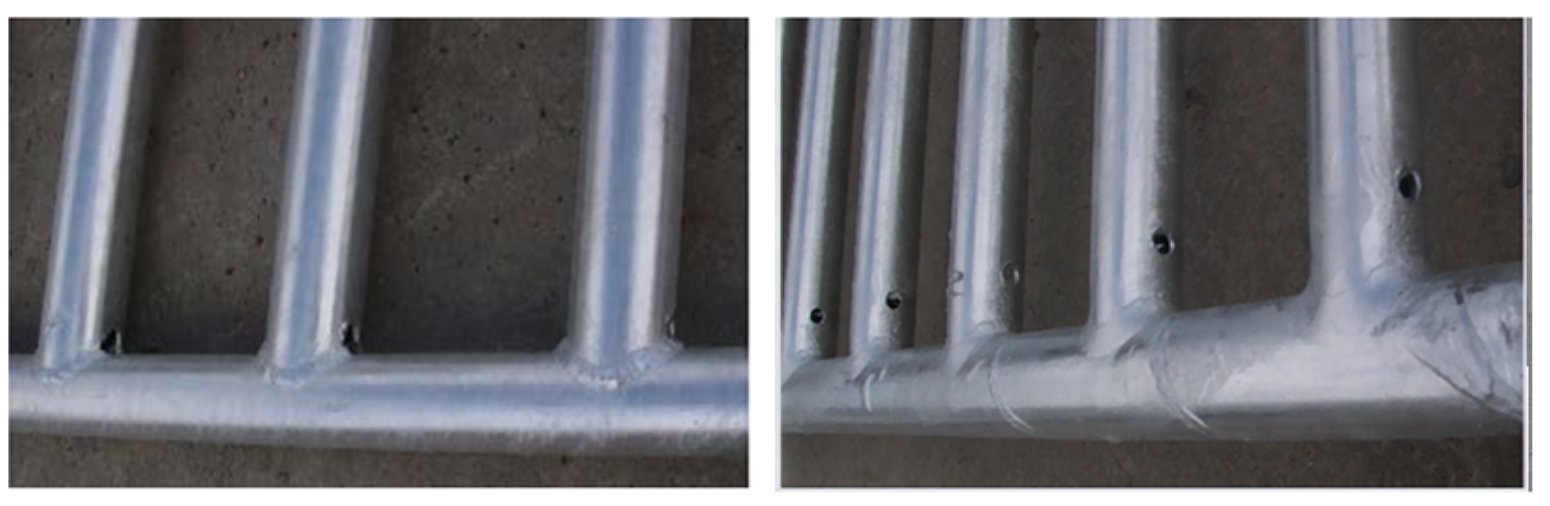
For improved venting and drainage it is recommended to specify more and/or larger holes than defined by ASTM A385, place holes as close as possible to intersecting areas and welds (ideally within 1/2 in.), and specify drilled holes or smoothed holes to improve flow and ensure correct sizing. Vent holes can be plugged after galvanizing (Figure 12).
Dissimilar Metals
The combination of various building materials and metals can be used to achieve unique color, texture, and sheens, but efforts should be made to avoid galvanic corrosion with hot-dip galvanized steel. It is desirable to specify galvanized fasteners for galvanized connections, and nonconductive spacers when joining with other metals or metallic coatings. Generally, the combination of hot-dip galvanized steel and stainless steel or aluminum can be specified for interior AESS members or AESS in atmospheric environments with mild humidity and low air salinity.
High Strength Bolts
The Research Council on Structural Connections (RCSC) Specification for Structural Joints Using High-Strength Bolts excludes bolt Group 150 (ASTM F3125 Grade A490 and ASTM F3125 Grade F2280) from being hot-dip galvanized or mechanically galvanized. If the bolt is hot-dip galvanized, delayed brittle fracture in service is a potential concern due to the possible introduction of hydrogen during the chemical cleaning operation of the hot-dip galvanizing process. Research is in progress into whether this prohibition can be repealed. If dissimilar metals must be used to accommodate the specification of these fastener grades, it may be necessary mitigate against galvanic corrosion.